The ESP32 chip comes with 48 pins with multiple functions. Not all pins are exposed in all ESP32 development boards, and there are some pins that cannot be used.
There are many questions on how to use the ESP32 GPIOs. What pins should you use? What pins should you avoid using in your projects? This post aims to be a simple and easy to follow reference guide for the ESP32 GPIOs.
The figure below illustrates the ESP-WROOM-32 pinout. You can use it as a reference if you’re using an ESP32 bare chip to build a custom board:
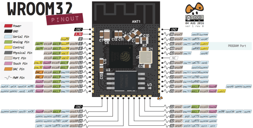
Note: not all GPIOs are accessible in all development boards, but each specific GPIO works in the same way regardless of the development board you’re using. If you’re just getting started with the ESP32, we recommend reading our guide: Getting Started with the ESP32 Development Board.
ESP32 Peripherals
The ESP32 peripherals include:
- 18 Analog-to-Digital Converter (ADC) channels
- 3 SPI interfaces
- 3 UART interfaces
- 2 I2C interfaces
- 16 PWM output channels
- 2 Digital-to-Analog Converters (DAC)
- 2 I2S interfaces
- 10 Capacitive sensing GPIOs
The ADC (analog to digital converter) and DAC (digital to analog converter) features are assigned to specific static pins. However, you can decide which pins are UART, I2C, SPI, PWM, etc – you just need to assign them in the code. This is possible due to the ESP32 chip’s multiplexing feature.
Although you can define the pins properties on the software, there are pins assigned by default as shown in the following figure (this is an example for the ESP32 DEVKIT V1 DOIT board with 36 pins – the pin location can change depending on the manufacturer).

Additionally, there are pins with specific features that make them suitable or not for a specific project. The following table shows what pins are best to use as inputs, outputs and which ones you need to be cautious.
The pins highlighted in green are OK to use. The ones highlighted in yellow are OK to use, but you need to pay attention because they may have unexpected behavior mainly at boot. The pins highlighted in red are not recommended to use as inputs or outputs.
| GPIO | Input | Output | Notes |
| 0 | pulled up | OK | outputs PWM signal at boot |
| 1 | TX pin | OK | debug output at boot |
| 2 | OK | OK | connected to on-board LED |
| 3 | OK | RX pin | HIGH at boot |
| 4 | OK | OK | |
| 5 | OK | OK | outputs PWM signal at boot |
| 6 | x | x | connected to the integrated SPI flash |
| 7 | x | x | connected to the integrated SPI flash |
| 8 | x | x | connected to the integrated SPI flash |
| 9 | x | x | connected to the integrated SPI flash |
| 10 | x | x | connected to the integrated SPI flash |
| 11 | x | x | connected to the integrated SPI flash |
| 12 | OK | OK | boot fail if pulled high |
| 13 | OK | OK | |
| 14 | OK | OK | outputs PWM signal at boot |
| 15 | OK | OK | outputs PWM signal at boot |
| 16 | OK | OK | |
| 17 | OK | OK | |
| 18 | OK | OK | |
| 19 | OK | OK | |
| 21 | OK | OK | |
| 22 | OK | OK | |
| 23 | OK | OK | |
| 25 | OK | OK | |
| 26 | OK | OK | |
| 27 | OK | OK | |
| 32 | OK | OK | |
| 33 | OK | OK | |
| 34 | OK | input only | |
| 35 | OK | input only | |
| 36 | OK | input only | |
| 39 | OK | input only |
Continue reading for a more detail and in-depth analysis of the ESP32 GPIOs and its functions.
Input only pins
GPIOs 34 to 39 are GPIs – input only pins. These pins don’t have internal pull-ups or pull-down resistors. They can’t be used as outputs, so use these pins only as inputs:
- GPIO 34
- GPIO 35
- GPIO 36
- GPIO 39
SPI flash integrated on the ESP-WROOM-32
GPIO 6 to GPIO 11 are exposed in some ESP32 development boards. However, these pins are connected to the integrated SPI flash on the ESP-WROOM-32 chip and are not recommended for other uses. So, don’t use these pins in your projects:
- GPIO 6 (SCK/CLK)
- GPIO 7 (SDO/SD0)
- GPIO 8 (SDI/SD1)
- GPIO 9 (SHD/SD2)
- GPIO 10 (SWP/SD3)
- GPIO 11 (CSC/CMD)
Capacitive touch GPIOs
The ESP32 has 10 internal capacitive touch sensors. These can sense variations in anything that holds an electrical charge, like the human skin. So they can detect variations induced when touching the GPIOs with a finger. These pins can be easily integrated into capacitive pads, and replace mechanical buttons. The capacitive touch pins can also be used to wake up the ESP32 from deep sleep.
Those internal touch sensors are connected to these GPIOs:
- T0 (GPIO 4)
- T1 (GPIO 0)
- T2 (GPIO 2)
- T3 (GPIO 15)
- T4 (GPIO 13)
- T5 (GPIO 12)
- T6 (GPIO 14)
- T7 (GPIO 27)
- T8 (GPIO 33)
- T9 (GPIO 32)
Learn how to use the touch pins with Arduino IDE: ESP32 Touch Pins with Arduino IDE
Analog to Digital Converter (ADC)
The ESP32 has 18 x 12 bits ADC input channels (while the ESP8266 only has 1x 10 bits ADC). These are the GPIOs that can be used as ADC and respective channels:
- ADC1_CH0 (GPIO 36)
- ADC1_CH1 (GPIO 37)
- ADC1_CH2 (GPIO 38)
- ADC1_CH3 (GPIO 39)
- ADC1_CH4 (GPIO 32)
- ADC1_CH5 (GPIO 33)
- ADC1_CH6 (GPIO 34)
- ADC1_CH7 (GPIO 35)
- ADC2_CH0 (GPIO 4)
- ADC2_CH1 (GPIO 0)
- ADC2_CH2 (GPIO 2)
- ADC2_CH3 (GPIO 15)
- ADC2_CH4 (GPIO 13)
- ADC2_CH5 (GPIO 12)
- ADC2_CH6 (GPIO 14)
- ADC2_CH7 (GPIO 27)
- ADC2_CH8 (GPIO 25)
- ADC2_CH9 (GPIO 26)
Learn how to use the ESP32 ADC pins:
Note: ADC2 pins cannot be used when Wi-Fi is used. So, if you’re using Wi-Fi and you’re having trouble getting the value from an ADC2 GPIO, you may consider using an ADC1 GPIO instead, that should solve your problem.
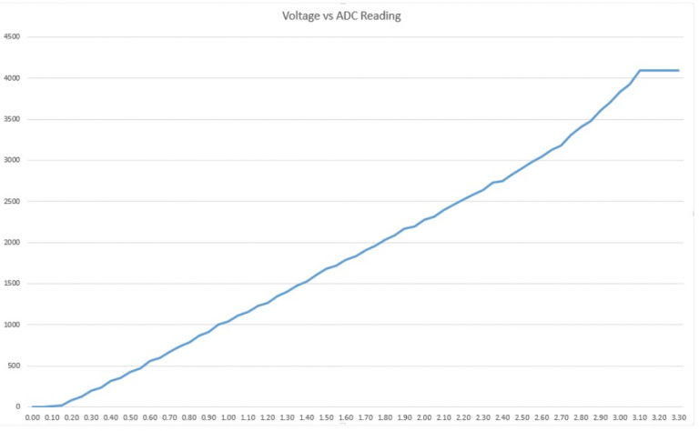
The ADC input channels have a 12 bit resolution. This means that you can get analog readings ranging from 0 to 4095, in which 0 corresponds to 0V and 4095 to 3.3V. You also have the ability to set the resolution of your channels on the code, as well as the ADC range.
The ESP32 ADC pins don’t have a linear behavior. You’ll probably won’t be able to distinguish between 0 and 0.1V, or between 3.2 and 3.3V. You need to keep that in mind when using the ADC pins. You’ll get a behavior similar to the one shown in the following figure.
Digital to Analog Converter (DAC)
There are 2 x 8 bits DAC channels on the ESP32 to convert digital signals into analog voltage signal outputs. These are the DAC channels:
- DAC1 (GPIO25)
- DAC2 (GPIO26)
RTC GPIOs
There is RTC GPIO support on the ESP32. The GPIOs routed to the RTC low-power subsystem can be used when the ESP32 is in deep sleep. These RTC GPIOs can be used to wake up the ESP32 from deep sleep when the Ultra Low Power (ULP) co-processor is running. The following GPIOs can be used as an external wake up source.
- RTC_GPIO0 (GPIO36)
- RTC_GPIO3 (GPIO39)
- RTC_GPIO4 (GPIO34)
- RTC_GPIO5 (GPIO35)
- RTC_GPIO6 (GPIO25)
- RTC_GPIO7 (GPIO26)
- RTC_GPIO8 (GPIO33)
- RTC_GPIO9 (GPIO32)
- RTC_GPIO10 (GPIO4)
- RTC_GPIO11 (GPIO0)
- RTC_GPIO12 (GPIO2)
- RTC_GPIO13 (GPIO15)
- RTC_GPIO14 (GPIO13)
- RTC_GPIO15 (GPIO12)
- RTC_GPIO16 (GPIO14)
- RTC_GPIO17 (GPIO27)
Learn how to use the RTC GPIOs to wake up the ESP32 from deep sleep: ESP32 Deep Sleep with Arduino IDE and Wake Up Sources
PWM
The ESP32 LED PWM controller has 16 independent channels that can be configured to generate PWM signals with different properties. All pins that can act as outputs can be used as PWM pins (GPIOs 34 to 39 can’t generate PWM).
To set a PWM signal, you need to define these parameters in the code:
- Signal’s frequency;
- Duty cycle;
- PWM channel;
- GPIO where you want to output the signal.
Learn how to use ESP32 PWM with Arduino IDE: ESP32 PWM with Arduino IDE
I2C
The ESP32 has two I2C channels and any pin can be set as SDA or SCL. When using the ESP32 with the Arduino IDE, the default I2C pins are:
- GPIO 21 (SDA)
- GPIO 22 (SCL)
If you want to use other pins, when using the wire library, you just need to call:
Wire.begin(SDA, SCL);
Learn more about I2C communication protocol with the ESP32 using Arduino IDE: ESP32 I2C Communication (Set Pins, Multiple Bus Interfaces and Peripherals)
SPI
By default, the pin mapping for SPI is:
| SPI | MOSI | MISO | CLK | CS |
| VSPI | GPIO 23 | GPIO 19 | GPIO 18 | GPIO 5 |
| HSPI | GPIO 13 | GPIO 12 | GPIO 14 | GPIO 15 |
Interrupts
All GPIOs can be configured as interrupts.
Learn how to use interrupts with the ESP32:
Strapping Pins
The ESP32 chip has the following strapping pins:
- GPIO 0
- GPIO 2
- GPIO 4
- GPIO 5 (must be HIGH during boot)
- GPIO 12 (must be LOW during boot)
- GPIO 15 (must be HIGH during boot)
These are used to put the ESP32 into bootloader or flashing mode. On most development boards with built-in USB/Serial, you don’t need to worry about the state of these pins. The board puts the pins in the right state for flashing or boot mode. More information on the ESP32 Boot Mode Selection can be found here.
However, if you have peripherals connected to those pins, you may have trouble trying to upload new code, flashing the ESP32 with new firmware or resetting the board. If you have some peripherals connected to the strapping pins and you are getting trouble uploading code or flashing the ESP32, it may be because those peripherals are preventing the ESP32 to enter the right mode. Read the Boot Mode Selection documentation to guide you in the right direction. After resetting, flashing, or booting, those pins work as expected.
Pins HIGH at Boot
Some GPIOs change its state to HIGH or output PWM signals at boot or reset. This means that if you have outputs connected to these GPIOs you may get unexpected results when the ESP32 resets or boots.
- GPIO 1
- GPIO 3
- GPIO 5
- GPIO 6 to GPIO 11 (connected to the ESP32 integrated SPI flash memory – not recommended to use).
- GPIO 14
- GPIO 15
Enable (EN)
Enable (EN) is the 3.3V regulator’s enable pin. It’s pulled up, so connect to ground to disable the 3.3V regulator. This means that you can use this pin connected to a pushbutton to restart your ESP32, for example.
GPIO current drawn
The absolute maximum current drawn per GPIO is 40mA according to the “Recommended Operating Conditions” section in the ESP32 datasheet.
ESP32 Built-In Hall Effect Sensor
The ESP32 also features a built-in hall effect sensor that detects changes in the magnetic field in its surroundings.
Wrapping Up
We hope you’ve found this reference guide for the ESP32 GPIOs useful. If you have more tips about the ESP32 GPIOs, please share by writing a comment down below.
If you’re just getting started with the ESP32, we have some great content to get started:
Thanks for reading.

26 thoughts on “ESP32 Pinout Reference: Which GPIO pins should you use?”